Video: Fibre Optics in the LAN and Data Centre

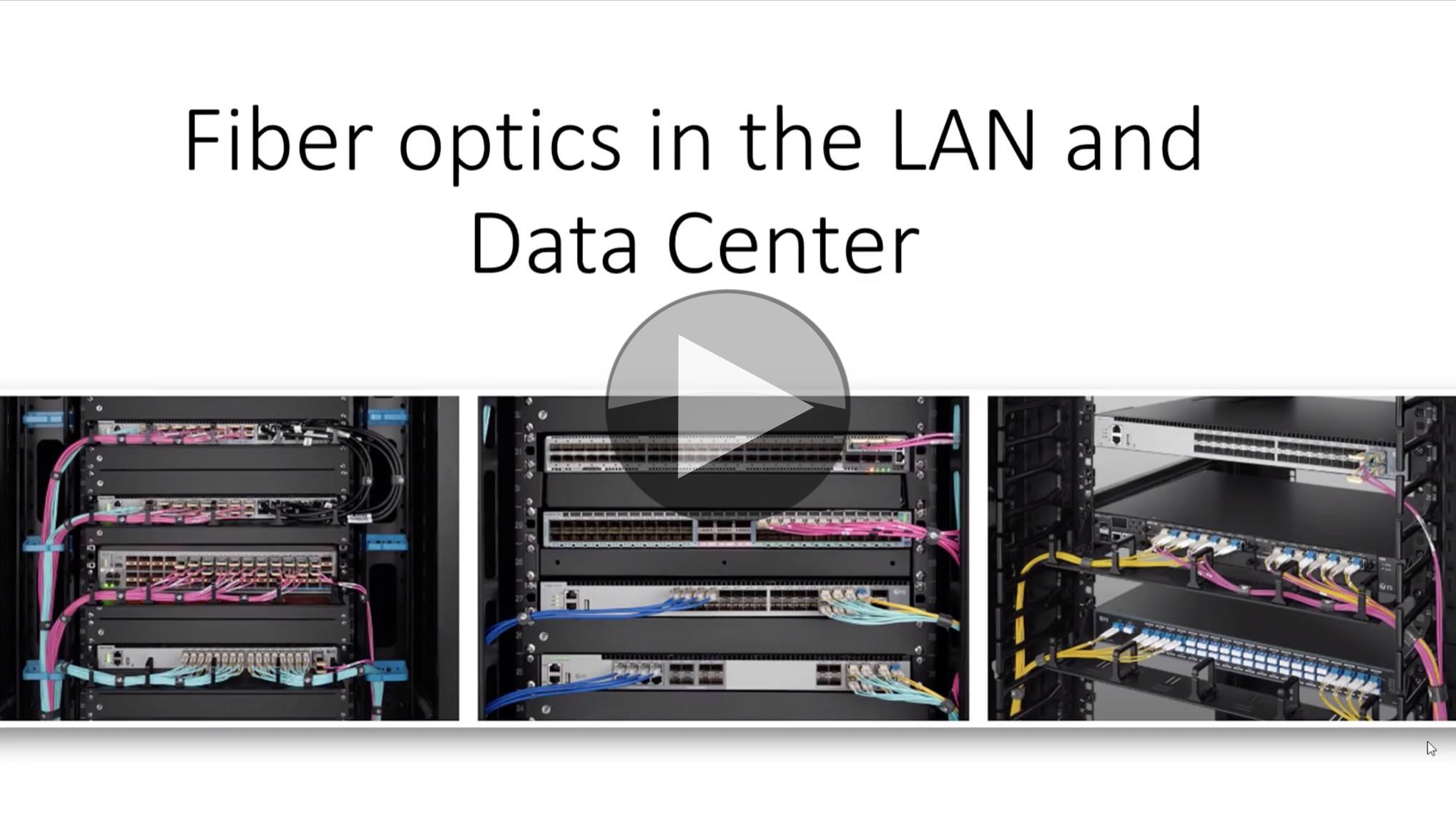
Fibres are the lifeblood of the major infrastructure broadcasters have today. But do you remember your SC from your LC connectors? Do you know which cable types are allowed in permenant installations? Did you know you can damage connectors by mating the wrong fibre endings? For some buildings, there’s only one fibre and connector type making patch cable selection all the easier. However there are always exceptions and when it comes to ordering more, do you know what to look out for to get exactly the right ones?

This video from Lowell Vanderpool takes a swift, but comprehensive, look at fibre types, connector types, light budget, ferrule types and SFPs. Delving straight in, Lowell quickly establishes the key differences between single-mode and multi-mode fibre with the latter using wider-diameter fibres. This keeps the costs down, but compared to single-mode fibre can’t transmit as far. Due to their cost, multi-mode fibres are common within the datacentre so Lowell takes us through the multimode cable types from the legacy OM1 to the latest OM5 cable.

OM1 cable was rated for 1GB, but the currently used OM3 and 4 fibre types can carry 10Gb up to 550m. Multimode fibres are typically colour-coded with OM3 an 4 being ‘aqua’. OM5 is the latest cable to standardised which can support Short Wavelength Division Multiplexing (SWDM) whereby 4 frequencies are sent down the same fibre giving an overall bandwidth of 10Gbx4 = 40GbE. For longer-distance, the yellow OS1 and, more recently, OS2 fibre types will achieve up to 10km distance.

Lowell explains that whilst 10km is far enough for many inter-building links, the distance quoted is a maximum which excludes the losses incurred as light leaves one fibre and enters another at connection points. Lowell has an excellent graphic which shows the overall light ‘budget’, how each connector represents a major drop in signal and how each interface will also reflect small amounts of the signal back up the fibre.

Having dealt with the inside of the cables, Lowell brings up the important topic of the outer jacket. All cables have different options for the outer jacket (for electrical cables, usually called insulation). These outer jackets allow for varying amounts of flexibility, water-tightness and armouring. Sometimes forgotten is that they have also got different properties in the event of fire. Depending on where a cable is, there are different rules on how flame retardant the cable can be. For instance, in the plenum of a room (false ceiling/wall) and a riser there are different requirements than patching between racks. Some areas keeping smoke low is important, in others ensuring fire doesn’t travel between areas is the aim so Lowell cautions us to check the local regulations.

The final part of the video covers connectors, ferrules and SFPs. Connectors come in many types, although as Lowell points out, LC is most popular in server rooms. LC connectors can come in pairs, locked together and called ‘duplex’ or individually, known as ‘simplex’. Lowell looks at pretty much every type of connector you might encounter from the legacy, metal bayonet & screw connectors (FC, ST) to the low-insertion loss, capped EC2000 connector for single mode cables and popular for telco applications. Lowell gives a close look at MPT and MPO connectors which combine 1×12 or 2×12 fibres into one connector making for a very high capacity connection. We also see how the fibres can be broken out individually at the other end into a breakout cassette.

The white, protruding end to a connector is called the ferrule and contains the fibre in the centre. The solid surround is shaped and polished to minimise gaps between the two fibre ends and to fully align the fibre ends themselves. Any errors will lead to loss of light due to it spilling out of the fibre or to excessive light bouncing back down the cable. Lowell highlights the existence of angled ferrules which will cause damage if mated with flat connectors.

The video finishes with a detailed talk through the make up of an SFP (Small Form-factor Pluggable) transceiver looking and what is going on inside. We see how the incoming data needs to be serialised, how heat dissipation and optical lanes are handled plus how that affects the cost.

Watch now!
Speaker

Lowell Vanderpool Lowell Vanderpool
Technical Trainger,
Lowell Vanderpool YouTube Channel

Video: IP-based Networks for UHD and HDR Video

If you get given a video signal, would you know what type it was? Life used to be simple, an SD signal would decode in a waveform monitor and you’d see which type it was. Now, with UHD and HDR, this isn’t all the information you need. Arguably this gets easier with IP and is possibly one of the few things that does. This video from AIMS helps to clear up why IP’s the best choice for UHD and HDR.

John Mailhot from Imagine Communications joins Wes Simpson from LearnIPVideo.com to introduce us to the difficulties wrangling with UHD and HDR video. Reflecting on the continued improvement of in-home displays’ ability to show brighter and better pictures as well as the broadcast cameras’ ability to capture much more dynamic range, John’s work at Imagine is focussed on helping broadcasters ensure their infrastructure can enable these high dynamic range experiences. Streaming services have a slightly easier time delivering HDR to end-users as they are in complete control of the distribution chain whereas often in broadcast, particularly with affiliates, there are many points in the chain which need to be HDR/UHD capable.

John starts by looking at how UHD was implemented in the early stages. UHD, being twice the horizontal and twice the vertical resolution of HD is usually seen as 4xHD, but, importantly, John points out that this is true for resolution but, as most HD is 1080i, it also represents a move to 1080p, 3Gbps signals. John’s point is that this is a strain on the infrastructure which was not necessarily tested for initially. Given the UHD signal, initially, was carried by four cables, there is now 4 times the chance of a signal impairment due to cabling.

Square Division Multiplexing (SQD) is the ‘most obvious’ way to carry UHD signals with existing HD infrastructure. The picture is simply cut into four quarters and each quarter is sent down one cable. The benefit here is that it’s easy to see which order the cables need to be connected to the equipment. The downsides included a frame-buffer delay (half a frame) each time the signal was received, difficulties preventing drift of quadrants if they were treated differently by the infrastructure (i.e. there was a non-synced hand-off). One important problem is that there is no way to know an HD feed is from a UHD set or just a lone 3G signal.

2SI, two-sample interleave, was another method of splitting up the signal which was standardised by SMPTE. This worked by taking a pair of samples and sending them down cable 1, then the next pair down cable 2, the pair of samples under the first pair went down cable 3 then the pair under 2 went down 4. This had the happy benefit that each cable held a complete picture, albeit very crudely downsampled. However, for monitoring applications, this is a benefit as you can DA one feed and send this to a monitor. Well, that would have been possible except for the problem that each signal had to maintain 400ns timing with the others which meant DAs often broke the timing budget if they reclocked. It did, however, remove the half-field latency burden which SQD carries. The main confounding factor in this mechanism is that looking at the video from any cable on a monitor isn’t enough to understand which of the four feeds you are looking at. Mis-cabling equipment leads to subtle visual errors which are hard to spot and hard to correct.

Enter the VPID, the Video Payload ID. SD SDI didn’t require this, HD often had it, but for UHD it became essential. SMPTE ST 425-5:2019 is the latest document explaining payload ID for UHD. As it’s version five, you should be aware that older equipment may not parse the information in the correct way a) as a bug and b) due to using an old standard. The VPID carries information such as interlaced/progressive, aspect ratio, transfer characteristics (HLG, SDR etc.), frame rate etc. John talks through some of the common mismatches in interpretation and implementation of VPID.

12G is the obvious baseband solution to the four-wires problem of UHD. Nowadays the cost of a 12G transceiver is only slightly more than 3G ones, therefore 12G is a very reasonable solution for many. It does require careful cabling to ensure the cable is in good condition and not too long. For OB trucks and small projects, 12G can work well. For larger installations, optical connections are needed, one signal per fibre.

The move to IP initially went to SMPTE ST 2022-6, which is a mapping of SDI onto IP. This meant it was still quite restrictive as we were still living within the SDI-described world. 12G was difficult to do. Getting four IP streams correctly aligned, and all switched on time, was also impractical. For UHD, therefore SMPTE ST 2110 is the natural home. 2110 can support 32K, so UHD fits in well. ST 2110-22 allows use of JPEG XS so if the 9-11Gbps bitrate of UHDp50/60 is too much it can be squeezed down to 1.5Gbps with almost no latency. Being carried as a single video flow removes any switch timing problems and as 2110 doesn’t use VPID, there is much more flexibility to fully describe the signal allowing future growth. We don’t know what’s to come, but if it’s different shapes of video rater, new colour spaces or extensions needed for IPMX, these are possible.

John finishes his conversation with Wes mentioning two big benefits of moving to IT-based infrastructure. One is the ability to use the free Wireshark or EBU List tools to analyse video. Whilst there are still good reasons to buy test equipment, the fact that many checks can be done without expensive equipment like waveform monitors is good news. The second big benefit is that whilst these standards were being made, the available network infrastructure has moved from 25 to 100 to 400Gbps links with 800Gbps coming in the next year or two. None of these changes has required any change in the standards, unlike with SDI where improvements in signal required improvements in baseband. Rather, the industry is able to take advantage of this new infrastructure with no effort on our part to develop it or modify the standards.

Watch now!
Speakers

John Mailhot John Mailhot
Systems Architect, IP Convergence,
Imagine Communications
Wes Simpson Wes Simpson
RIST AG Co-Chair, VSF
President & Founder, LearnIPvideo.com

Video: Keeping Time with PTP

The audio world has been using PTP for years, but now there is renewed interest thanks to its inclusion in SMPTE ST 2110. Replacing the black and burst timing signal (and for those that used it, TLS), PTP changes the way we distribute time. B&B was a waterfall distribution, PTP is a bi-directional conversation which, as a system, needs to be monitored and should be actively maintained.

Michael Waidson from Telestream (who now own Tektronix) brings us the foundational basics of PTP as well as tips and tricks to troubleshoot your PTP system. He starts by explaining. the types of messages which are exchanged between the clock and the device as well as why all these different messages are necessary. We see that we can set the frequency at which the announce, sync and follow-up messages. The sync and follow-up messages actually contain the time. When a device receives one of these messages, it needs to respond with a ‘delay request’ in order to work out how much of a delay there is between it and the grand master clock. This will result in it receiving a delay response. On top of these basic messages, there is a periodic management message which can contain further information such as daylight savings time or drop-frame information.

Michael moves on to looking at troubleshooting highlighting the four main numbers to check: The domain value, grandmaster ID, message rates and the communication mode. PTP is a global standard used in many industries. To make PTP most useful to the broadcast industry, SMPTE ST 2059 defines values to use for message repetition (4 per second for announce messages, 8 for sync, delay request and delay response). ST 2059 also defines how devices can determine the phase of any broadcast signal for any given time which is the fundamental link needed to ensure all devices keep synchronicity.

Another good tip from Michael is if you see the grandmaster MAC changing between the grandmasters on the system, this indicates it’s no receiving any announce messages so is initiating the Best Master Clock Algorithm (BMCA) and trying the next grandmaster. Some PTP monitoring equipment including from Meinberg and from Telestream can show the phase lag of the PTP timing as well as the delay between the primary and secondary grandmaster – the lower the better.

A talk on PTP can’t avoid mentioning boundary clocks and transparent switches. Boundary clocks take on much of the two-way traffic in PTP protecting the grandmasters from having to speak directly to all the, potentially, thousands of devices. Transparent switches, simply update the time announcements with the delay for the message to move through the switch. Whilst this is useful in keeping the timing accurate, it provides no protection for the grandmasters. He finishes video ends with a look at how to check PTP messages on the switch.

Watch now!
Speakers

Michael Waidson Michael Waidson
Application Engineer
Telestream (formerly Tektronix)

Video: HTTP over QUIC is the next generation

There’s a lot to like about HTTP/3 from encryption as standard, faster set-up time, better compression and promises better throughput by removing head-of-line blocking. A new protocol making its way through the IETF and based on QUIC, this could have a real impact on anyone involved in streaming.

wolfSSL’s Daniel Stenberg and cURL maintainer, talks to us about HTTP/3 but starts at the beginning with HTTP 1 and 1/1. He outlines some of the issues we had in 1997 such as head-of-line blocking and ephemeral TCP connections. Zooming forward to 2005, HTTP/2 comes on the scene with a single HTTP connection, thus removing the significant overhead of ephemeral TCP connections. HTTP/2 went with a ‘streamed’ connection and could have multiple such streams but one thing that wasn’t solved was head-of-line blocking.

Before moving beyond HTTP/2, Daniel describes the problems that have set in due to ‘ossification’, that is to say, that the routers that time forgot which are still on very old, and often buggy TCP implementations. Innovating is very difficult if replacing the TCP within even a subset of boxes would mean I wasn’t able to send my website globally.

Addressing this ‘ossification’ issue, QUIC has stepped in. Developed on UDP instead of TCP QUIC solves a number of problems. First off, moving from TCP to UDP allows the protocol to live in userspace making it easier to update. Working on UDP instead of TCP means that the protocol regains control of the retransmissions allowing for something more efficient than TCP’s strict acknowledgement rules.

So QUIC becomes the transport layer of HTTP/3. Freeing ourselves from TCP, Daniel explains, allows us to remove the TCP head-of-line blocking problem. HTTP/3 on QUIC brings with it faster handshakes and a connection ID. This connection ID allows you to change IP addresses and still maintain your connection which is a significant improvement on what has gone before. Daniel continues by explaining more benefits of QUICK and HTTP/3 such as its encryption and the ability to have multiple streams.

Daniel finishes up outlining eight challenges for HTTP/3. These include the fact that up to 7% of QUICK attempts fail, dealing with ‘fall back’ algorithms, UDP having seen historically low usage and are less optimised as well as the downsides of userland protocol stacks being that it’s harder to get a standard.

Watch now!
Download the presentation
Speakers

Daniel Stenberg Daniel Stenberg
curl master, wolfSSL
main author,