Video: Keeping Time with PTP

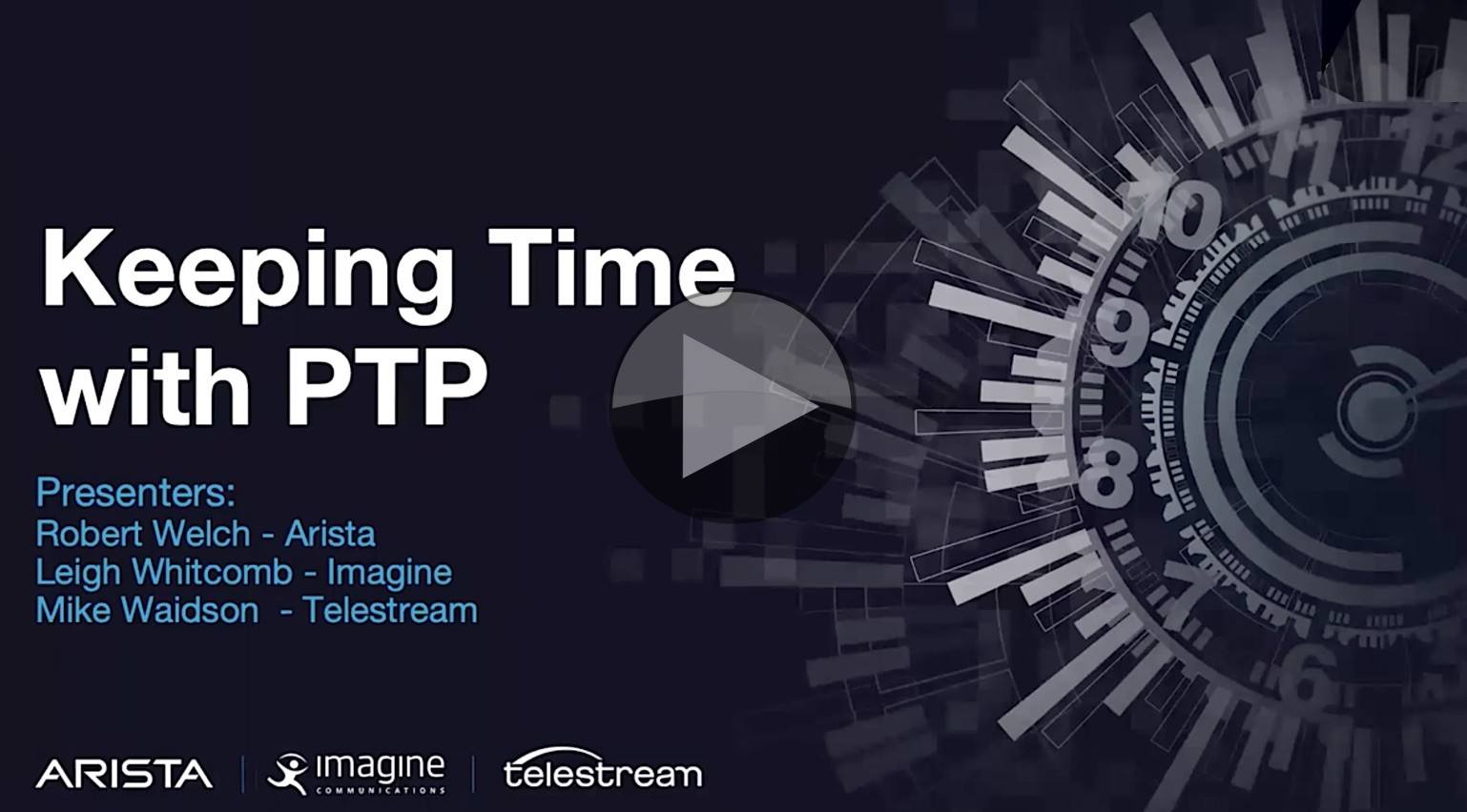
Different from his talk of the same name we covered last week, Mike Waidson from Telestream explains the fundamentals of PTP joined by Leigh Whitcomb from Imagine Communications and Robert Welch from Arista. Very few PTP talks include a live BCMA quiz plus, with more time than the IP Showcase talks, this is a well-paced, deep look into the basics.

Mike starts by reviewing how the measurement of time has been more and more accurately measured with us now, typically using atomic clocks. In the TV-domain analogue video used signals for B&B which gave frequency information in the subcarrier and allowed frequency locking and to keep in sync with other signals. NTP has allowed computers and routers on IP networks to keep lock allowing sub-millisecond synchronisation over LANs. Now we have IEEE 1588 PTP which harnesses hardware for maximum precision providing sub-microsecond precision.

Traditionally an SPG would create many different synchronising signals, distributed by DAs. With PTP however, the idea is creating a single time signal on to the network (as well as older signals if necessary). Although, the important thing to remember is that PTP both sends and receives data from the endpoints. GPS is made from 31 active satellites of which only 4 are needed for a lock. But other systems such as the Russian GLONASS, the Chinese BAIDU Navigational system or the European Galileo can also be used, sometimes in conjunction with each other to improve locking speed or give resilience.

Mike and his co-hosts give an overview of the standards that make all this possible, starting with the PTP standard itself IEEE 1588-2019 which is added to by SMPTE 2059. The latter is two standards that, together ensure broadcast devices can usefully harness PTP which is a general, cross-industry standard and track all signals back to a single point in time in 1970. Whilst this may seem extreme, the benefit of doing this is that if we know that all possible types of signal were in-phase at this one point in time, we can extrapolate how each signal should be phased now and use that information to synchronise the system. Upcoming to PTP, we hear, are standardised ways to monitor PTP plus additional security around the standard.

The next section looks at the types of Grandmaster and the fact that each clock works in its own domain. Typically, all your system will be in the same domain, but if you have incompatible situations such as older Dante networks or if you want to have a testing environment, you can use domains to separate your equipment. The standard, as defined by SMPTE 2059 is 127.

Mike then looks at the different types of PTP Message types: Announce, Sync & Follow up, Delay Request, Delay Response and Management Messages (broadcast information, drop second, time zone etc.) He then brings some of these up in Wireshark and talks us through the structure and what can be found within.

The most original part of the talk is the live walkthrough of three different scenarios where Leigh and Robert talk through their thinking on which clock will be the grandmaster and for what reason. This comes down to their understanding of the order of precedence of the metrics such as the manually-allotted priority, then the class of clock, clock accuracy and other values. One value worth remembering is that if your clock is locked to GPS it will have a class of 6, but if it then loses lock, it will become 7.

PTP talks are not complete without an explanation of the sync message exchanges needed to actually determine the time (and the relative delays in order to compute it) as well as the secondary clock types, boundary and transparent. Boundary clocks take on much of the two-way traffic in PTP protecting the grandmasters from having to speak directly to all the, potentially, thousands of devices. Transparent switches, simply update the time announcements with the delay for the message to move through the switch. Whilst this is useful in keeping the timing accurate, it provides no protection for the grandmasters.

Before the talk finishes with a Q&A, the team finish by explaining the difference between operating in unicast and multicast, prioritising PTP traffic using the differentiated services protocol and adding redundancy to the PTP system.

Watch now!
Free registration required
Speakers

Robert Welch Robert Welch
Technical Solultions Lead,
Arista
Leigh Whitcomb Leigh Whitcomb
Principal Engineer.
Imagine
Michael Waidson Mike Waidson
Application Engineer,
Telestream

Video: Hacking ATSC 3.0

ATSC’s effort to bring IP into over-the-air broadcast has been long in the making and its deployment in South Korea along with the ITU’s inclusion of it in it’s list of recommended digital broadcast standards is a testament to it gaining acceptance. But as US broadcasters continue with test broadcasts and roll-outs in 2020, what security problems arise when IP’s included in the mix?

Acting is a great network security primer, this talk from Texas A&M’s Wayne Pecena, explains the premise and implications of creating and maintaining security in your broadcast plant. Starting by documenting the high profile attacks on broadcasters over the years, Wayne hones in on the reasons they should care from the obvious, omnipresent threat of ‘dead air’ to ‘loss of trust’ which is particularly motivating in recent years as we have seen state actors move to influence, not disrupt the normal course of life, in low-key, long-burn persistent attacks.

The talk hinges around the ‘AIC’ triad, comprising confidentiality, integrity and availability which are the three core aspects of data to protect. Integrity involves ensuring that the data are not altered either in transit or, indeed, in storage. Confidentiality revolves around ensuring that access control is maintained at all levels including physical, network-level and application live. Finally availability encompasses the fact that if the data isn’t available to the people who need it, the whole thing is pointless. Therefore supporting the availability side of the triangle includes thinking about redundancy and disaster recovery procedures.

Wayne, who is also the president of the Society of Broadcast Engineers, explains some of the attributes of a secure system which starts with security policies. These are the outer layer of any secure environment detailing how the many other layers of security will be managed and applied. Other aspects of a secure environment are appropriately layered and segmented network design, to limit what is available to anyone who does penetrate part of a system, access controls and logging.

After looking at the IETF and IEEE standards bodies, we see how the standard network models overlay neatly on the ATSC layered model with networking in the centre of them all. This leads in to a brief introduction to ‘IP’ in the sense of the the IP protocol on which are based TCP/IP and UDP/IP, between them central to most network communications around the world.

As we see how a small hole in defences can be slowly changed and enlarged allowing the attacker to move forward and create another hole in the next layer, Wayne talks about the types of security threats such malware, denial of service attacks and, of course, inside threats such as your employees themselves being complicit.

As the talk draws to a close we look at how this plays out in the real world talking through diagrams of broadcasters’ systems and how mitigations might play out on premise before talking cloud security. As the threat model in the cloud is different, Wayne explains the best practices to ensure safety and how these and the other security technologies used on the internet keep ATSC 3.0 secure including TLS secure certificate and the use of DNSSEC

The talk finishes with a look at security in the home whether that be with the myriad of consumer media consumption devices or items from the ‘internet of things’.

Watch now!
Speaker

Wayne Pecena Wayne Pecena
Director of Engineering, KAMU TV/FM at Texas A&M University
President, Society of Broadcast Engineers AKA SBE

Webinar: An Overview of the ATSC 3.0 Interactive Environment

Allowing viewers to interact with television services is an obvious next step for the IP-delivered ATSC service. Taking cues from the European HbbTV standard, the aim here is to make available as many ways as practical for viewers to direct their viewing in order to open up new avenues for television channels and programme creators.

Mark Corl is chair of the TG3/S38: Specialist Group on Interactive Environment. Its aim is to support interactive applications and their companion devices. It has produced the A/344 standard which is based on W3C technologies with APIs which support the needs of broadcast television. It describes the Interactive Environment Content Display model allowing video to be mixed with app graphics as a composite display. Mark is also part of the ATSC group TG3-9 which looks at how the different layers of ATSC 3.0 can communicate with each other where necessary.

From the TG3 group, too, is the Companion Device Concepts A/338 standards document which details discovery of second devices such as smartphones and enabling them to communicate with the ATSC 3.0 receiver.

In this webinar from the IEEE BTS, Mark marries an understanding of these documents with the practical aspects of deploying interactive broadcaster applications to receivers including some of the motivations to do this, such as improving revenue through the introduction of Dynamic Ad Insertion and personalisation.

Register now!
Speakers

Mark Corl Mark Corl
Chair, TG3/S38 Specialist Group on Interactive Environment
Co-chair, TG3-9 AHG on Interlayer Communications in the ATSC 3.0 Ecosystem
Senior Vice President, Emergent Technology Development, Triveni Digital

Webinar: ATSC 3.0 Physical Layer and Data Link Layer Overview

ATSC 3.0 brings IP delivery to over-the-air TV marking a major change in delivery to the home. For the first time video, audio and other data is all delivered as network streams allowing services available to TV viewers at home to modernise and merge with online streaming services better matching the viewing habits of today. ATSC 3.0 deployments are starting in the USA and it has already been rolled out in South Korea for the XXIII Olympic Winter Games in 2018.

Whilst the move to IP is transformational, ATSC 3.0 delivers a whole slew of improvements to the ATSC standard for RF, bandwidth, Codecs and more. In this, the first of three webinars from the IEEE BTS focussing in on ATSC 3.0, we look at the physical layer with Luke Fay, Chair of the ATSC 3.0 group and also a Senior Manager of Technical Standards at Sony.

Click to register: Wednesday, 15th January, 2020. 11am ET / 16:00 GMT

What is the Physical Layer?
The physical layer refers to the method data gets from one place to another. In this case, we’re talking about transmission by air, RF. Whilst this isn’t, in some ways, as physical as a copper cable, we have to remember that, at a basic level, communication is about making a high voltage in place A change the voltage in place B. The message physically moves from A to B and the medium it uses and the way it manipulates that medium are what we refer to as the physical layer.

In this webinar, Luke will talk about System Discovery and Signalling, defined by document A/321 and the Physical Layer Protocol defined by A/322. Both freely available from the ATSC website. The webinar will finish with a Q&A. Let’s take a deeper look at some of the topics which will be covered.

Choice of modulation

ATSC 3.0 has chosen the COFDM modulation scheme over the previous 8VSB, currently used for first-generation ATSC broadcasts, to deliver data over the air from the transmitter. COFDM, stands for Coded Orthogonal Frequency Devision Multiplexing and has become the go-to modulation method for digital transmissions including for DAB, DAB+ and the DVB terrestrial, satellite and cable standards.

One of the reasons for its wide adoption is that COFDM has guard bands; times when the transmitter is guaranteed not to send any data. This allows the receiver some time to receive any data which comes in late due to multi-path reflections or any other reason. This means that for COFDM, you get better performance if you run a network of nearby transmitters on the same frequency – known as a Single Frequency Network (SFN). A transmitters signal from further away will arrive later, and if in the guard interval, will be used to re-inforce the directly received signal. This means that, counter-intuitively from analogue days, running an SFN actually helps improve reception.

Multiple operating points to match the business case
Another important feature of ATSC 3.0 at the physical layer is the ability to be able to choose the robustness of the signal and have multiple transmissions simultaneously using different levels of robustness. These multiple transmissions are called pipes. As many of us will be familiar with, when transmitting a high bandwidth, the signal can be fragile and easily corrupted by interference. Putting resilience into the signal uses up bandwidth either due using some of the capacity to put error checking and error recovery data in or just by slowing down the rate the signal is sent which, of course, means not as many bits can be sent in the same time window.

Because bandwidth and resilience are a balancing act with each one fighting against the other, it’s important for stations to be able to choose what’s right for them and their business case. Having a high robustness signalm for penetration indoors can be very useful for targeting reception on mobile devices and ATSC 3.0 can actually achieve reception when the signal is below the noise, i.e. a negative signal to noise ratio. A higher bandwidth service delivering UHD at around 20Mbps can be achieved, however, by using 64 instead of 16 QAM.

Register now!
Speaker

Luke Fay
Chairman, ATSC Technology Group 3,
Senior Manager Technical Standards, Sony Home Entertainment & Sound Products – America