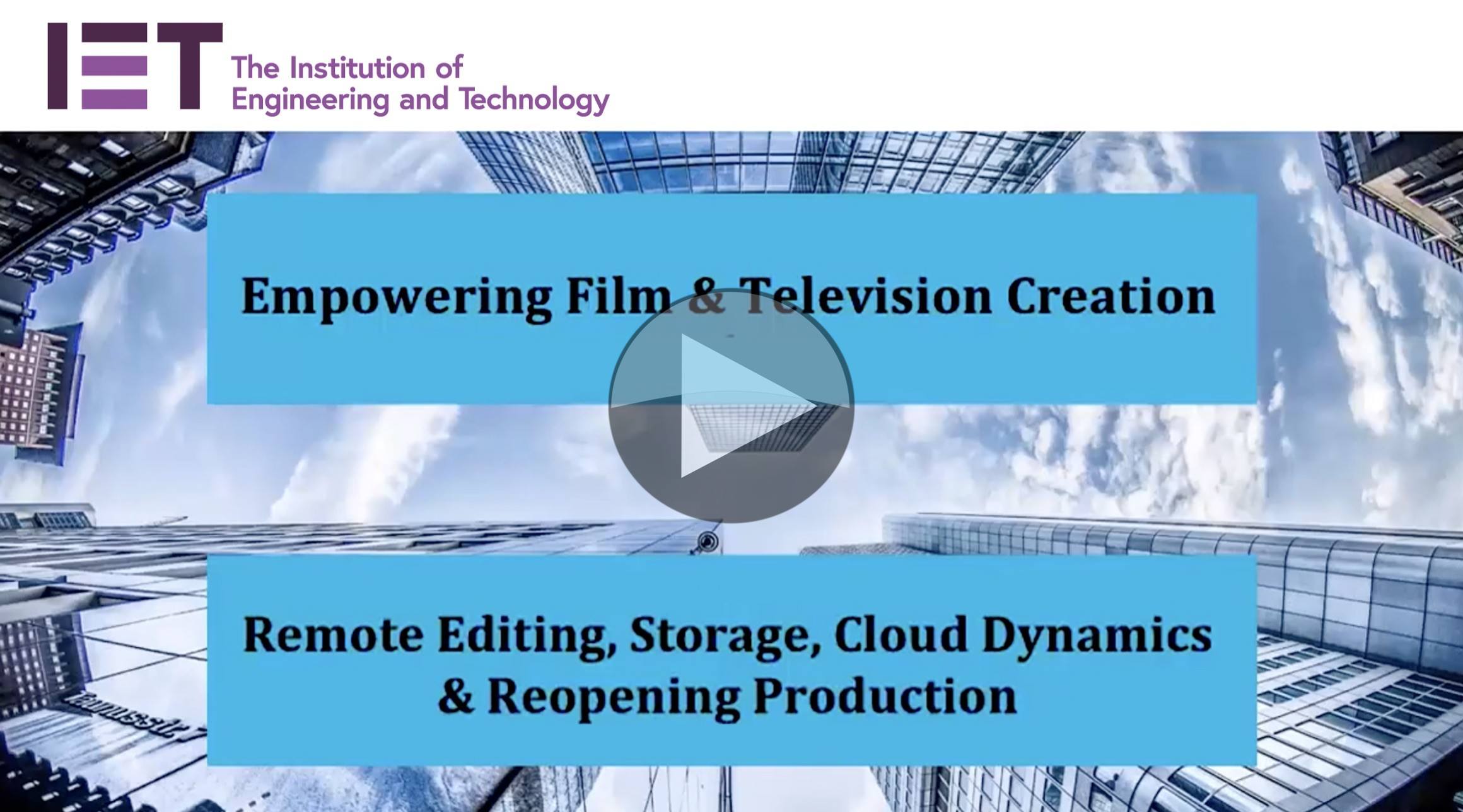
Video: Remote editing, storage, cloud dynamics & reopening production

The rug was pulled from under the feet of the production industry due to the pandemic, both in film and television. The scramble to finish projects and to fill TV schedules has resulted in a lot of creative ideas and a surge in remote editing. This panel looks at the benefits of this work and considers whether this will continue to be done in the future when the restrictions are lifted.

In this video, we hear from Sony, Teradici, Lou Wirth Productions, EditShare and PADEM Group on the gaping hole in workflows left by the pandemic and how the industry has bridged the gap with remote editing.

Moderated by IET Media Exec director Allan McLennan from PADEM group, we hear answers to questions like “What are the challenges moving to remote editing?”, “Can Remote Editing open up diversity in this part of the industry?” and features a look to the future in terms of new technologies for meeting the streaming demand.

“One of the challenges with a technology transition is people often need a motivation”

Stephen Tallamy, EditShare

“It’s easy to keep doing the thing you used to do until you’re forced to do it,” explains EditShare’s Stephen Tallamy. But the panel doesn’t see the pandemic as just something that forced a change, rather they see the benefits in the move towards remove editing and remote collaboration. David Rosen from Sony was positive saying that “Creative resources can be anywhere and the elimination of having to move those people to where the content it…is a significant advantage.” From his perspective, increasing numbers of customers have cloud as part of their workflow.

“Never again.” My customers are saying, “Never again will I be in a situation where I cannot get access to. my content.”

David Rosen, Sony

The panel’s discussion moves to remote editing, the practice of giving editors access to remote computers which run the editing software and have access to the relevant media. The editor’s local computer then becomes a window on to the edit suite in a different building, or in the cloud. Ian Main from Teradici, explains that a company can open an edit station up to an editor who could be anywhere in the world which is why this is such an important part of the solution to enabling work to continue in an emergency. Teradici specialises in developing and deploying high-performance remote control of PCs and Stephen Tallamy speaks from the experience of enabling remote editing using Teradici for enabling remote editing workflows on AWS and other cloud providers and data centres.

“The production side shut down, but the post-production side accelerated.”

Ian Main, Teradici
Lou Wirth, award-winning editor and producer, joins the panel as someone who has continued to edit locally. “For producers who were forced to go into a remote editing situation, they may have always been on the fence about it”, Lou says, “…If it was a good experience, they would see the advantages of it and continue.” Indeed the consensus does seem to be that much of what’s happening now will be fed back into workflows of the future even when restrictions are lifted.

Listen to the whole discussion which includes a look ahead to IBC.

Watch now!
Speakers

Ian Main Ian Main
Technical Marketing Principle,
Teradici
David Rosen David Rosen
VP, Cloud Applications & Solutions,
Sony
Stephen Tallamy Stephen Tallamy
Chief Technology Officer,
EditShare
Lou Wirth Lou Wirth
Head Story Editor,
Lou Wirth Productions
Allan McLennan Moderator: Allan McLennan
Chief Executive, Global Market Technologist, PADEM Media Group,
Executive Board Director, IET Media technology network

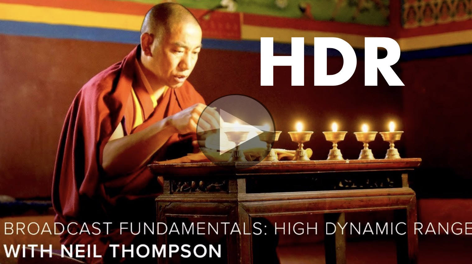
Video: Broadcast Fundamentals: High Dynamic Range

Update: Unfortunately CVP choose to take down this video within 12 hours of this article going live. But there’s good news if you’re interested in HDR. Firstly, you can find the outline and some of the basics of the talk explained below. Secondly, at The Broadcast Knowledge there are plenty of talks discussing HDR! Here’s hoping CVP bring the video back.

Why is High Dynamic Range is like getting a giraffe on a tube train? HDR continues its ascent. Super Bowl LIV was filmed in HDR this year, Sky in the UK has launched HDR and many of the big streaming services support it including Disney+, Prime and Netflix. So as it slowly takes its place, we look at what it is and how it’s achieved in the camera and in production.

Neil Thompson, an Sony Independent Certified Expert, takes a seat in the CVP Common Room to lead us through HDR from the start and explain how giraffes are part of the equation. Dynamic Range makes up two thirds of HDR, so he starts by explaining what it is with an analogy to audio. When you turn up the speakers so they start to distort, that’s the top of your range. The bottom is silence – or rather what you can hear over the quiet hiss that all audio systems have. Similarly in cameras, you can have bright pixels which are a different brightness to the next which represents the top of your range, and the dithering blacks which are the bottom of your range. In video, if you go too bright, all pixels become white even if the subject’s brightness varies which the equivalent of the audio distortion.

With the basic explanation out of the way, Neil moves on to describing the amount or size of dynamic range (DR) which can be done either in stops, contrast ratio or signal to noise ratio. He compares ‘stops’ to a bucket of water with some sludge at the bottom where the range is between the top of sludge and the rim of the bucket. One stop, he explains, is a halving of the range. With the bucket analogy, if you can go half way down the bucket and still hit clear water, you have 1 stop of dynamic range. If you can then go a quarter down with clean water, you have 2 stops. By the time you get to 1/32nd you have 5 stops. If going to 1/64 of the height of the bucket means you end up in the sludge, your system has 5 stops of dynamic range. Reducing the sludge so there’s clear water at 1/64th the height, which in cameras means reducing the noise in the blacks, is one way of increasing the dynamic range of your acquisition.

Update: Unfortunately CVP choose to take down this video within 12 hours of this article going live. But there’s good news if you’re interested in HDR. Firstly, you can find the outline and some of the basics of the talk explained below. Secondly, at The Broadcast Knowledge there are plenty of talks discussing HDR! Here’s hoping CVP bring the video back.

If you would like to know how lenses fit into the equation of gathering light, check out this talk from Cannon’s Larry Thorpe.

Neil looks next at the range of light that we see in real life from sunlight to looking at the stars at night. Our eye has 14 stops of range, though with our iris, we can see the equivalent of 24 stops. Similarly, cameras use an iris to regulate the light incoming which helps move the restricted dynamic range of the camera into the right range of brightness for our shot.

Of course, once you have gathered the light, you need to display it again. Displays’ ability to produce light is measured in ‘nits’, which is the amount of light per metre squared. Knowing how many nits a displays helps you understand the brightness it can show with 1000 nits, currently, being a typical HDR display. Of course, dynamic range is as much about the blacks as the brightness. OLED screens are fantastic at having low blacks, though their brightness can be quite low. LEDs, conversely, Neil explains, can go very bright but the blacks do suffer. You have to also take into account the location of a display device to understand what range it needs. In a dim gallery you can spend longer caring about the blacks, but many places are so bright, the top end is much more important than the blacks.

With the acquisition side explained, Neil moves on to transmission of HDR and it’s like getting a giraffe on a tube train. Neil relates the already familiar ‘log profiles’. There are two HDR curves, known as transfer functions, PQ from Dolby and HLG (Hybrig Log Gamma). Neil looks at which profiles are best for each part of the production workflow and then explains how PQ differs from HLG in terms of expressing brightness levels. In HLG, the brightest part of the signal tells the display device to output as brightly as it can. A PQ signal, however, reserves the brightest signal for 10,000 nits – far higher than displays available today. This means that we need to do some work to deal with the situation where your display isn’t as bright as the one used to master the signal. Neil discusses how we do that with metadata.

Finishing off the talk, Neil takes questions from the audience, but also walks through a long list of questions he brought along including discussing ‘how bright is too bright?’, what to look for in an engineering monitor, lighting for HDR and costs.

Watch now!
Speakers

Neil Thompson Neil Thompson
Freelance Engineer & Trainer

Video: Using AMWA IS-06 for Flow Control on Professional Media Networks

In IP networks multicast flow subscription is usually based on a combination of IGMP (Internet Group Management Protocol) and PIM (Protocol Independent Multicast) protocols. While PIM allows for very efficient delivery of IP multicast data, it doesn’t provide bandwidth control or device authorisation.

To solve these issues on SMPTE ST 2110 professional media networks the NMOS IS-06 specification has been developed. It relies on a Software-Defined Networking, where traffic management application embedded in each single switch or router is replaced by a centralised Network Controller. This controller manages and monitors the whole network environment, making it bandwidth aware.

NMOS IS-06 specification provides a vendor agnostic Northbound interface from Network Controller to Broadcast Controller. IS-06 in conjunction with IS-04 (Discovery and Registration) and IS-05 (NMOS Device Connection Management) allows Broadcast Controller to automatically set up media flows between endpoints on the network, reserve bandwidth for flows and enforce network security. Broadcast Controller is also able to request network topology information from Network Controller, which can be used to create a user friendly graphic representation of the flows in the network.

In this presentation Rob Porter from Sony Europe explains the basics of NMOS IS-06, showing in details how setting up media flows with this specification fits into the IS-04 / IS-05 workflow. Rob emphasise that all AMWA NMOS specifications are completely open and available to anyone, allowing for interoperability between broadcast and network devices from different manufacturers.

The next speaker, Sachin Vishwarupe from Cisco Systems, focuses on the future works on IS-06, including provisioning feedback (such as insufficient bandwidth, no route available from sender to receiver or no management connectivity), flow statistics, security and grouping (similar to ”salvo” in SDI world).

There is also a discussion on extension of IS-06 specification for Network Address Translation (NAT), which would help to resolve problems caused by address conflicts e.g. when sharing resources between facilities.

You can find the slides here.

Watch now!

Speakers

Rob Porter Rob Porter
Project Manager – Advanced Technology Team
Sony Europe
Sachin Vishwarupe
Principal Engineer
Cisco Systems

Webinar: ATSC 3.0 Physical Layer and Data Link Layer Overview

ATSC 3.0 brings IP delivery to over-the-air TV marking a major change in delivery to the home. For the first time video, audio and other data is all delivered as network streams allowing services available to TV viewers at home to modernise and merge with online streaming services better matching the viewing habits of today. ATSC 3.0 deployments are starting in the USA and it has already been rolled out in South Korea for the XXIII Olympic Winter Games in 2018.

Whilst the move to IP is transformational, ATSC 3.0 delivers a whole slew of improvements to the ATSC standard for RF, bandwidth, Codecs and more. In this, the first of three webinars from the IEEE BTS focussing in on ATSC 3.0, we look at the physical layer with Luke Fay, Chair of the ATSC 3.0 group and also a Senior Manager of Technical Standards at Sony.

Click to register: Wednesday, 15th January, 2020. 11am ET / 16:00 GMT

What is the Physical Layer?
The physical layer refers to the method data gets from one place to another. In this case, we’re talking about transmission by air, RF. Whilst this isn’t, in some ways, as physical as a copper cable, we have to remember that, at a basic level, communication is about making a high voltage in place A change the voltage in place B. The message physically moves from A to B and the medium it uses and the way it manipulates that medium are what we refer to as the physical layer.

In this webinar, Luke will talk about System Discovery and Signalling, defined by document A/321 and the Physical Layer Protocol defined by A/322. Both freely available from the ATSC website. The webinar will finish with a Q&A. Let’s take a deeper look at some of the topics which will be covered.

Choice of modulation

ATSC 3.0 has chosen the COFDM modulation scheme over the previous 8VSB, currently used for first-generation ATSC broadcasts, to deliver data over the air from the transmitter. COFDM, stands for Coded Orthogonal Frequency Devision Multiplexing and has become the go-to modulation method for digital transmissions including for DAB, DAB+ and the DVB terrestrial, satellite and cable standards.

One of the reasons for its wide adoption is that COFDM has guard bands; times when the transmitter is guaranteed not to send any data. This allows the receiver some time to receive any data which comes in late due to multi-path reflections or any other reason. This means that for COFDM, you get better performance if you run a network of nearby transmitters on the same frequency – known as a Single Frequency Network (SFN). A transmitters signal from further away will arrive later, and if in the guard interval, will be used to re-inforce the directly received signal. This means that, counter-intuitively from analogue days, running an SFN actually helps improve reception.

Multiple operating points to match the business case
Another important feature of ATSC 3.0 at the physical layer is the ability to be able to choose the robustness of the signal and have multiple transmissions simultaneously using different levels of robustness. These multiple transmissions are called pipes. As many of us will be familiar with, when transmitting a high bandwidth, the signal can be fragile and easily corrupted by interference. Putting resilience into the signal uses up bandwidth either due using some of the capacity to put error checking and error recovery data in or just by slowing down the rate the signal is sent which, of course, means not as many bits can be sent in the same time window.

Because bandwidth and resilience are a balancing act with each one fighting against the other, it’s important for stations to be able to choose what’s right for them and their business case. Having a high robustness signalm for penetration indoors can be very useful for targeting reception on mobile devices and ATSC 3.0 can actually achieve reception when the signal is below the noise, i.e. a negative signal to noise ratio. A higher bandwidth service delivering UHD at around 20Mbps can be achieved, however, by using 64 instead of 16 QAM.

Register now!
Speaker

Luke Fay
Chairman, ATSC Technology Group 3,
Senior Manager Technical Standards, Sony Home Entertainment & Sound Products – America