Video: NMOS IS-07, GPI Replacement and Much, Much More…

GPI was not without its complexities, but the simplicity of its function in terms of putting a short or a voltage on a wire, is unmatched by any other system we use in broadcasting. So the question here is, how do we do ‘GPI’ with IP given all the complexity, and perceived delay, in networked communication. CTO of Pebble Beach, Miroslav Jeras, is here to explain.

The key to understanding the power of the new specification for GPI from NMOS called IS-07 is to realise that it’s not trying to emulate DC electronics. Rather, by adding the timing information available from the PTP clock, the GPI trigger can now become extremely accurate – down to the audio sample – meaning you can now use GPI to indicate much more detailed situations. On top of that, the GPI messages can contain a number of different data types, which expands the ability of these GPI messages and also helps interoperability between systems.

Miroslav explains the ways in which these messages are passed over the network and how IS-07 interacts with the other specifications such as IS-05 and BCP-002-01. He explains how IS-07 was used in the Techno Project – tpc, Zurich and then takes us through a range of different examples of how IS-07 can be used including synchronisation of the GUI and monitoring as well as routing based on GPI.

Watch now! | Download the slides

Speakers

Miroslav Jeras Miroslav Jeras
CTO,
Pebble Beach Systems

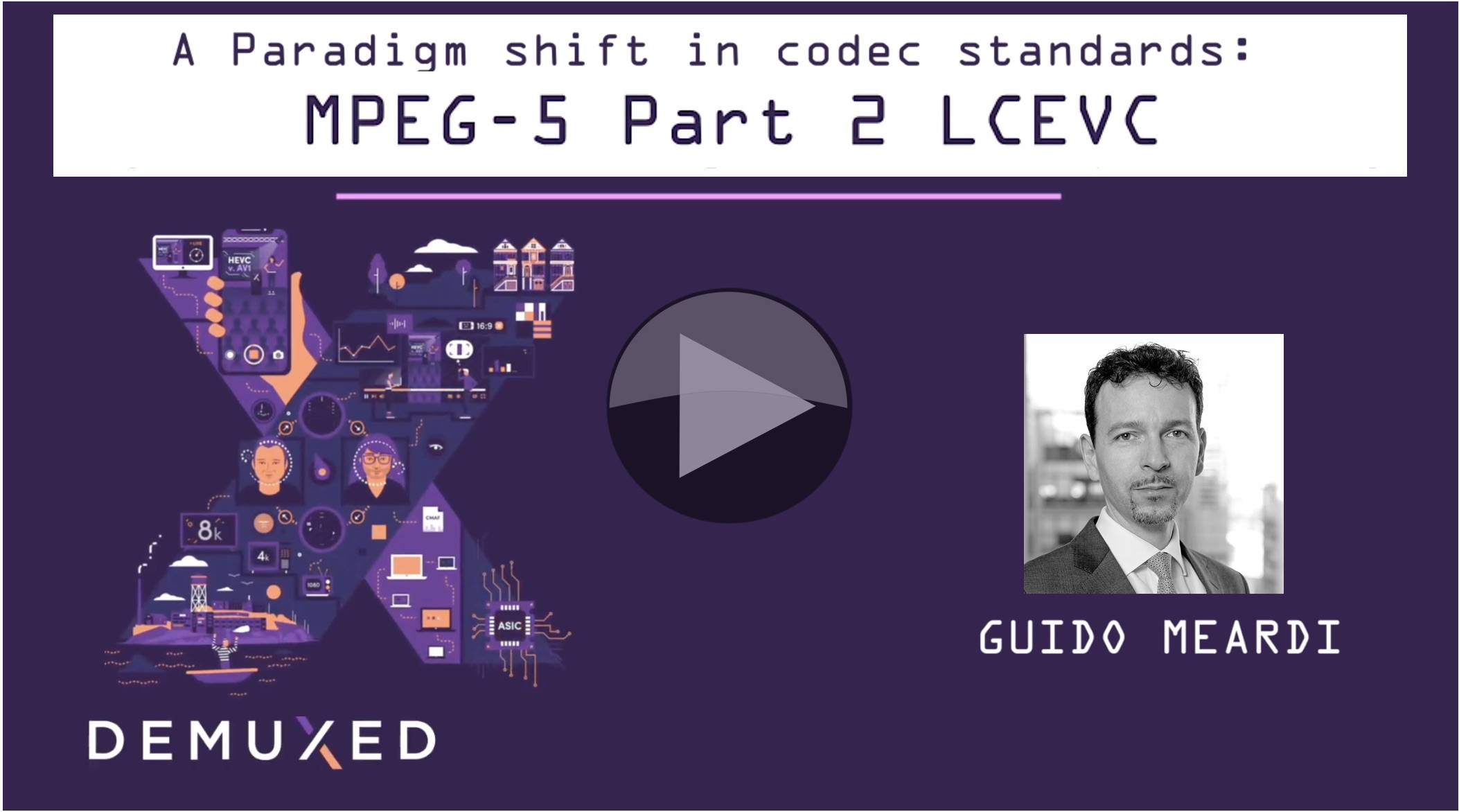
Video: A paradigm shift in codec standards – MPEG-5 Part 2 LCEVC

LCEVC (Low Complexity Enhancement Video Coding) is a low-complexity encoder/decoder is in the process of standardisation as MPEG-5 Part 2. Instead of being an entirely new codec, LCEVC improves detail and sharpness of any base video codec (e.g., AVC, HEVC, AV1, EVC or VVC) while lowering the overall computational complexity expanding the range of devices that can access high quality and/or low-bitrate video.

The idea is to use a base codec at lower resolution and add additional layer of encoded residuals to correct artifacts. Details are encoded with directional decomposition transform using a very small matrix (2×2 or 4×4) which is efficient at preserving high frequencies. As LCEVC uses parallelized techniques to reconstruct the target resolution, it encodes video faster than a full resolution base encoder.

LCEVC allows for enhancement layers to be added on top of existing bitstreams, so for example UHD resolution can be used where only HD was possible before thanks to sharing decoding between the ASIC and CPU. LCEVC can be decoded via light software processing, and even via HTML5.

In this presentation Guido Meardi from V-Nova introduces LCEVC and answers a few imporant question including: is it suitable for very high quality / bitrates compression and will it work with future codecs. He also shows performance data and benchmarks for live and VoD streaming, illustrating the compression quality and encoding complexity benefits achievable with LCEVC as an enhancement to H.264, HEVC and AV1.

Watch now!

Speaker

Guido Meardi
CEO and Co-Founder
V-Nova Ltd.

Webinar: ATSC 3.0 Physical Layer and Data Link Layer Overview

ATSC 3.0 brings IP delivery to over-the-air TV marking a major change in delivery to the home. For the first time video, audio and other data is all delivered as network streams allowing services available to TV viewers at home to modernise and merge with online streaming services better matching the viewing habits of today. ATSC 3.0 deployments are starting in the USA and it has already been rolled out in South Korea for the XXIII Olympic Winter Games in 2018.

Whilst the move to IP is transformational, ATSC 3.0 delivers a whole slew of improvements to the ATSC standard for RF, bandwidth, Codecs and more. In this, the first of three webinars from the IEEE BTS focussing in on ATSC 3.0, we look at the physical layer with Luke Fay, Chair of the ATSC 3.0 group and also a Senior Manager of Technical Standards at Sony.

Click to register: Wednesday, 15th January, 2020. 11am ET / 16:00 GMT

What is the Physical Layer?
The physical layer refers to the method data gets from one place to another. In this case, we’re talking about transmission by air, RF. Whilst this isn’t, in some ways, as physical as a copper cable, we have to remember that, at a basic level, communication is about making a high voltage in place A change the voltage in place B. The message physically moves from A to B and the medium it uses and the way it manipulates that medium are what we refer to as the physical layer.

In this webinar, Luke will talk about System Discovery and Signalling, defined by document A/321 and the Physical Layer Protocol defined by A/322. Both freely available from the ATSC website. The webinar will finish with a Q&A. Let’s take a deeper look at some of the topics which will be covered.

Choice of modulation

ATSC 3.0 has chosen the COFDM modulation scheme over the previous 8VSB, currently used for first-generation ATSC broadcasts, to deliver data over the air from the transmitter. COFDM, stands for Coded Orthogonal Frequency Devision Multiplexing and has become the go-to modulation method for digital transmissions including for DAB, DAB+ and the DVB terrestrial, satellite and cable standards.

One of the reasons for its wide adoption is that COFDM has guard bands; times when the transmitter is guaranteed not to send any data. This allows the receiver some time to receive any data which comes in late due to multi-path reflections or any other reason. This means that for COFDM, you get better performance if you run a network of nearby transmitters on the same frequency – known as a Single Frequency Network (SFN). A transmitters signal from further away will arrive later, and if in the guard interval, will be used to re-inforce the directly received signal. This means that, counter-intuitively from analogue days, running an SFN actually helps improve reception.

Multiple operating points to match the business case
Another important feature of ATSC 3.0 at the physical layer is the ability to be able to choose the robustness of the signal and have multiple transmissions simultaneously using different levels of robustness. These multiple transmissions are called pipes. As many of us will be familiar with, when transmitting a high bandwidth, the signal can be fragile and easily corrupted by interference. Putting resilience into the signal uses up bandwidth either due using some of the capacity to put error checking and error recovery data in or just by slowing down the rate the signal is sent which, of course, means not as many bits can be sent in the same time window.

Because bandwidth and resilience are a balancing act with each one fighting against the other, it’s important for stations to be able to choose what’s right for them and their business case. Having a high robustness signalm for penetration indoors can be very useful for targeting reception on mobile devices and ATSC 3.0 can actually achieve reception when the signal is below the noise, i.e. a negative signal to noise ratio. A higher bandwidth service delivering UHD at around 20Mbps can be achieved, however, by using 64 instead of 16 QAM.

Register now!
Speaker

Luke Fay
Chairman, ATSC Technology Group 3,
Senior Manager Technical Standards, Sony Home Entertainment & Sound Products – America

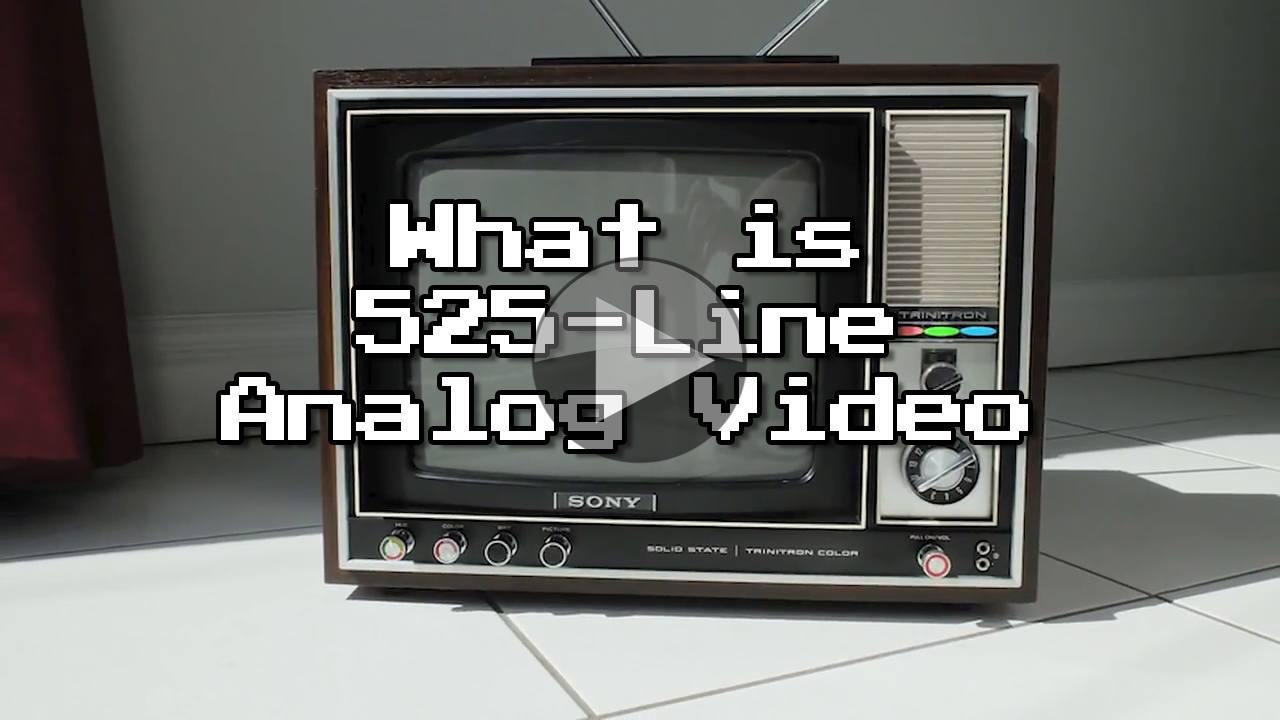
Video: What is 525-Line Analog Video?

With an enjoyable retro feel, this accessible video on understanding how analogue video works is useful for those who have to work with SDI rasters, interlaced video, black and burst, subtitles and more. It’ll remind those of us who once knew, a few things since forgotten and is an enjoyable primer on the topic for anyone coming in fresh.

Displaced Gamers is a YouTube channel and their focus on video games is an enjoyable addition to this video which starts by explaining why analogue 525-line video is the same as 480i. Using a slow-motion video of a CRT (Cathode Ray Tube) TV, the video explains the interlacing technique and why consoles/computers would often use 240p.

We then move on to timing looking at the time spent drawing a line of video, 52.7 microseconds, and the need for horizontal and vertical blanking. Blanking periods, the video explains are there to cover the time that the CRT TV would spend moving the electron beam from one side of the TV to the other. As this was achieved by electromagnets, while these were changing their magnetic level, and hence the position of the beam, the beam would need to be turned off – blanked.

The importance of these housekeeping manoeuvres for older computers was that this was time they could use to perform calculations, free from the task of writing data in to the video buffer. But this was not just useful for computers, broadcasters could use some of the blanking to insert data – and they still do. We see in this video a VHS video played with the blanking clearly visible and the data lines flashing away.

For those who work with this technology still, for those who like history, for those who are intellectually curious and for those who like reminiscing, this is an enjoyable video and ideal for sharing with colleagues.

Watch now!
Speaker

Chris Kennedy Chris Kennedy
Displaced Gamers,YouTube Channel