Video: QoE Impact from Router Buffer sizing and Active Queue Management

Netflix take to the stage at Demux to tell us about the work they’ve been doing to understand and reduce latency by looking at the queue management of their managed switches. As Tony Orme mentioned yesterday, we need buffers in IP systems to allow synchronous parts to interact. Here, we’re looking at how the core network fabric’s buffers can get in
the way of the main video flows.

Te-Yuan Huang from Netflix explains their work in investigating buffers and how best to use them. She talks about the flows that occur due to the buffer models of standard switches i.e. waiting until the buffer is full and then dropping everything else that comes in until the buffer is emptied. There is an alternative method, Active Queue Management (AQM), called FQ-CoDel which drops packets based on probability before the buffer is dropped. By carefully choosing the probability, you can actually improve buffer handling and the impact it has on latency.

Te-Yuan shows us results from tests that her team has done which show that the FQ-CoDel specification does, indeed, reduce latency. After showing us the data, she summarises saying that FQ-CoDel improves playback and QOE.

Watch now!
Speaker

Te-Yuan Huang Te-Yuan Huang
Engineering Manager (Adaptive Streaming),
Netflix

Video: IP Fundamentals For Broadcast Seminar Part III

‘IP’ is such a frequently used term, that is real meaning and context easily gets lost. As we saw from Wayne’s first and seminars, IP stands on top of ethernet and the cabling needed to support the whole network stack. But as we see from the subtitle, this where we get to virtual addressing which, as an abstraction layer, offers us a lot of flexibility. IP, the Internet Protocol, is where much of what we refer to as ‘networking’ happens, so it’s important to understand.

Wayne Pecena, long-standing staff member at Texas A&M University, goes straight into to IPV4 packet types. In the world of SMPTE ST-2110 and SMPTE ST-2022, this is important as much media traffic is sent multicast which is different to unicast and broadcast traffic. These three methods of sending data each have pros and cons. Unicast is the most well-known whereby packets are sent directly from the sender to a specific receiving device. Broadcast is, as the term suggests, a way of sending from one computer to all computers. This is great when you’re shouting out to another device to find out some key information about the network, but it can lead to disaster if all senders are doing this. For media use, multicast is where it’s at, allowing a sender to send to a group of receiving devices each of which opt in to this stream, just like you can opt in to a newsletter.

Wayne digs in to how an IPv4 packet is constructed looking at all parts of the header including the source and destination IP addresses. This leads us into looking at how an IP address is constructed. The trick with IP addresses and moving data from one network to another, we learn is in understanding which machines are on your local network (in which case you can use layer 2 Ethernet to send them data) and those that aren’t (in which case you need to use IP to pass on your message to the other network). This is done using subnets which is explained along with classes of addresses and class-less notation.

Once you know how to tell which network an address is in, this leads to the need to pass information from one to another opening up the topic of Network Address Translation (NAT). The typical example of NAT is that a message might come in to a public IP address on port 3000 which would then be sent to the internal network to a defined internal address on port 80. Wayne explains how this works and runs through examples.

For a network to keep track of which physical interfaces are where and have which IP address requires an ARP table which has been mentioned in previous seminars because it bridges both layer 2 and layer 3. Now we’re at layer 3, it’s time to go in for another look ahead of examining how DHCP workshop it assigns DNS addresses and how DNS itself works.

The next section steps into the world of diagnosis with ping and the ICMP protocol on which it is based. This leads in to explaining how trace route works, based on changing the TTL of the packet. The TTL is the Time To Live, which one way that a network knows it can drop a packet. This exists to protect networks from having packets which live forever and are constantly circling the network. However the TTL, in this situation, can be used to probe information about the network. Wayne explains the pros and the cons of ping and traceroute.

The seminar finishes by a look at routers, routing tables, routing protocols like IGP, EGP, OSPF, EIGRP and their peers.

Watch now!
Speaker
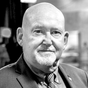
Wayne Pecena Wayne Pecena
Director of Engineering, KAMU TV/FM at Texas A&M University
President, Society of Broadcast Engineers AKA SBE

Video: Reinventing Intercom with SMPTE ST 2110-30

Intercom systems form the backbone of any broadcast production environment. There have been great strides made in the advancement of these systems, and matrix intercoms are very mature solution now, with partylines, IFBs and groups, wide range of connectivity options and easy signal monitoring. However, they have flaws as well. Initial cost is high and there’s lack of flexibility as system size is limited by the matrix port count. It is possible to trunk multiple frames, but it is difficult, expensive and takes rack space. Moreover, everything cables back to a central matrix which might be a single point of failure.

In this presentation, Martin Dyster from The Telos Alliance looks at the parallels between the emergence of Audio over IP (AoIP) standards and the development of products in the intercom market. First a short history of Audio over IP protocols is shown, including Telos Livewire (2003), Audinate Dante (2006), Wheatstone WheatNet (2008) and ALC Networks Ravenna (2010). With all these protocols available a question of interoperability has arisen – if you try to connect equipment using two different AoIP protocols it simply won’t work.

In 2010 The Audio Engineering Society formed the x192 Working Group which was the driving force behind the AES67. This standard was ratified in 2013 and allowed interconnecting audio equipment from different vendors. In 2017 SMPTE adapted AES67 as the audio format for ST 2110 standard.

Audio over IP replaces the idea of connecting all devices “point-to-point” with multicast IP flows – all devices are connected via a common fabric and all audio routes are simply messages that go from one device to another. Martin explains how Telos were inspired by this approach to move away from the matrix based intercoms and create a distributed system, in which there is no central core and DSP processing is built in intercom panels. Each panel contains audio mix engines and a set of AES67 receivers and transmitters which use multicast IP flows. Any ST 2110-30 / AES67 compatible devices present on the network can connect with intercom panels without an external interface. Analog and other baseband audio needs to be converted to ST 2110-30 / AES67.

Martin finishes his presentation by highlighting advantages of AoIP intercom systems, including lower entry and maintenance cost, easy expansion (multi studio or even multi site) and resilient operation (no single point of failure). Moreover, adaptation of multicast IP audio flows removes the need for DAs, patch bays and centralised routers, which reduces cabling and saves rack space.

Watch now!

Download the slides.

If you want to refresh your knowledge about AES67 and ST2110-30, we recomend the Video: Deep Dive into SMPTE ST 2110-30, 31 & AES 67 Audio presentation by Leigh Whitcomb.

Speaker

Martin Dyster
VP Business Development
The Telos Alliance

Video: IP Fundamentals For Broadcast Part II


After last week’s talk explaining networking from the real basics, Wayne Pecena is back to look at “where the good stuff is” in the next two layers of the OSI model.

Much of what live production needs happens in layers 2 and 3. At layer 2 we have Ethernet which defines how data is passed from switch to switch. Then at layer 3 we have the IP protocols, UDP and TCP which do nearly all of the heavy lifting getting our data from one place to another.

Wayne Pecena from Texas A&M University builds this talk around layer 2 specifically and starts by looking at the underlying protocols of Ethernet including collision detection. Given that the cabling is bi-directional, it’s possible for both ends to be sending data at the same time. This needs to be avoided, so the sending devices need to sense what’s happening on the wire and allow time for the other interface to finish.

Famously Ethernet has MAC addresses which is the way that this Layer 2 protocol deals with addressing the correct end point. Wayne shows the format these addresses follows and looks at the makeup of the frame which houses the data payload. The length of each segment of data is set with a maximum, but there is a high-throughput option called Jumbo Frames which increases efficiency for high bit rate applications by reducing the number of frames needing to be sent and therefore reducing the amount of header data sent.

A switch is an Ethernet device for connecting together multiple devices to communicate over Layer 2 and has a number of functions like learning MAC addresses, filtering frames and forwarding frames from one interface to another one. Switches can provide not only data but power to avoid having to run more than one cable. Usefully, Wayne walks us through the steps taken for one computer to send to another. Stepping through this mixture of ethernet and IP address is very useful to understand how to fault find, but also to see how layer 2 and 3 work so closely together.

Knowing the innards of a switch is vital to a full understanding of network behaviour. Wayne talks through a diagram of the what’s inside a switch showing that each NIC has its own set of buffers, a backplane (also known as ‘switch fabric’) and shared resources like a CPU. We see then how the switch learns the MAC addresses of everything connected to it and we see that, with the CPU and separating MAC address lists, a switch can create virtual lans, known as VLANs which allow a logical separation of interfaces that are on the same switch. It has the effect of creating multiple networks, that can’t speak to each other by default, on the same hardware and then allows the flexibility to add certain interfaces to multiple networks. VLANs are highly utilised in enterprise computing.

The talk finishes with a full description of how VLANs work and interact and 802.1Q VLAN tagging.

Watch now!

Wayne’s previous talk
Speaker

Wayne Pecena Wayne Pecena
Director of Engineering, KAMU TV/FM at Texas A&M University
President, Society of Broadcast Engineers AKA SBE